
Build a step sequencer for your digital synths!
In this tutorial, you will learn the basics of step sequencers, why they are useful, and how to build your own 8-10 step sequencer for your next synthesizer project.
Introduction
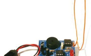
Building synthesizer circuits is fun & easy! With a couple of parts you can get for less than $5, you can make a simple circuit that will make some sweet synth sounds.
The most famous example of this is the Atari Punk Console (also known as the APC or Stepped Tone Generator), a beginner-friendly synthesizer circuit that utilizes a 556 dual timer chip (conveniently available at your local Radioshack, of all places) to generate a glitchy lo-fi noise.
While it is a great circuit that will bring a smile and encouragement to any audio electronics beginner, the novelty wears off fairly quick. You’ll find some sweet spots and maybe be able to get a cool tone every once in a while, but the output will be static and boring. To get any good sounds, you’ll find yourself tweaking the knobs for some dynamic output.
If only there was a way to make this circuit hands-free, dynamic, and capable of playing on its own, something musical…
Sequencing
What you need is a sequencer! By adding a periodic element to your digital synth circuitry, you will amaze yourself with the amount of control and flexibility you will have at your hands.
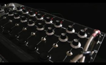
Sequencers come in all shapes and sizes, with different voltage outputs and control methods. We are going to use the simple Baby 10 Sequencer for a base circuit, and extend it so we get a really useful circuit.
Power Supply
Our 4017 circuit will be powered by +9V, which is a fairly modest voltage. I am assuming that you have built an Atari Punk Console, and are using it with a battery or a DC power supply.

Our circuit will use a voltage regulator to keep the circuit supplied by a steady +9V. Make sure to use a AC Adapter that outputs +12V or greater, as voltage regulators typically require ~+3V of headroom.
Clock
To make sure that our circuit operates synchronously, we are going to use a very simple circuit snippet to generate a clock pulse. Clock pulse generator circuits create a steady on/off state that allows multiple circuit blocks to execute their functions at a specified time interval.
For our 4017 Decade Counter, a clock pulse is essential for the output signal to advance in sequence.
Clock Control
When we build a simple NAND gate squarewave oscillator, we are guaranteed a fairly steady clock pulse for our circuit. But what if we want to stop our circuit? For instance, tuning the output potentiometers can be pretty painful if we try to attempt it while the 4017 advances through its decade sequence according to the clock beat.
What we need is a way to pause the circuit. And if the circuit is paused, we should have an ability to advance the sequence with the push of a button. And this should happen reliably.
By utilizing simple CMOS logic, we can achieve both a HOLD and a STEP-THROUGH functionality that will allow for maximum control by the sequencer user.
(NOTE: Due to the 4017’s limitations, we will only be able to step forward through the sequence. Check out UP/DOWN counters in the 4000 series of CMOS logic chips if you’re interested)
Output Buffering
Sequence Control Logic: Manual Step and Hold
A free-running 8 step sequencer is all well and good, but it lacks control. In most designs that I found online that were using the 4017 as the main circuit element, no attention was paid to this very significant feature.

The solution was simple: use logic gates to gate all clock signals to the 4017. Using this approach, multiple clock sources could be used (astable multivibrators [square wave oscillators], pushbutton switch) and the sequencer could be paused at any time for tuning of each step’s CV (Control Voltage).
Hold

The schematic above is a switch deboucer, a very important circuit element when interfacing your digital logic circuits with the mechanical outside world. If we were to use the switches without the 4093 NAND Schmitt Trigger, we would get switch bounce. Switch bounce is the physical action of a switch’s contacts actually bouncing off of each other before coming to rest. What seems like a instantaneous action to our senses is actually recognized by the ultra-fast digital circuits as multiple pulses. Not good, not good at all.
Schmitt Triggers only switch binary values (1=High or 0=Low) when the inputs meet certain corresponding high/low threshold values. Using an ordinary NAND gate would send our circuit into something called metastability, which is very bad when we’re concerned with having crisp user interfaces.
The resistor R1 keeps the input at a high logic level until a switch is activated, toggling the input to a low logic level. The capacitor C1 sends any quick pulses directly to ground and helps smooth out false triggering.
The output of this circuit without the switch being pressed is a logic 0. When the switch is pressed, the output switches to logic 1.
Two switches are shown in the diagram above, a momentary SPST and a toggle SPST. When depressed/toggled, either one will disable the clock signal and halt the sequencer at whatever step it is at. That’s exactly what we want.
Step

This circuit is very similar to the circuit above. Again, we have the very common switch debounce circuit. This time, there is only one switch, as we want our Step signal to be an arcade game style push->response type of action.
Refer back to the Sequencer Control Image. You’ll notice that the XOR (Exclusive OR) gate is fed directly into the 4017’s clock input (pin 14). This control logic only allows two separate ways to advance the clock sequence: the clock signal or the Step signal. When the clock signal is disabled via either of the two Hold switches, the Step signal is now active.
The Step signal can be thought of as a manual clock signal. Press the momentary switch S3 and the output of the circuit toggles from 0 to 1. This rising edge from 0 to 1 advances the 4017 sequencer to the next step. Holding the switch and releasing it will do nothing. The only signal the 4017 cares about is the next rising clock edge.
(This page is by no means complete, but will have information consistently added. For now, enjoy some of my notes and send me any questions, requests,etc., through the Contact page.)
External Resources:

I’m waiting and watching! I’m having a difficult time finding comprehensive tutorials/schematics for building a sequencer. Looking forward to the next episode!
Alex
First great placement to control a step sequencer!
So to build this do we need 4 NAND gates and 1 XOR?