
In the DIY audio electronics world, getting electricity to power your circuits is merely a matter of connecting the right wires and voltages to the right spots! In this tutorial, I hope that, by the end, you will have a firm grasp on how to make your own Center Negative power supply.
I will go step-by-step through how to construct a circuit that accepts a Center Negative AC Adapter and/or a 9V battery to supply power to your own circuits. Once the basic circuit has been constructed, I will show you how to modify it: add an ON-OFF switch, add a Power Status LED, and build a 5V voltage regulator circuit for your next breadboard experiment session or DIY design.
Overview
Although the majority of consumer electronic devices use a Center Positive AC-DC Adapter (commonly referred to as an AC adapter, wall wart, power cord) for their battery charging/ power supply, many audio electronics such as guitar pedals, analog synthesizers, pocket amplifiers and other music generators use the Center Negative power supply configuration. This appears to be either a clever engineering move for profit (“You have to use our special power supply”) or simply just a design issue. In reality, it’s not that limiting, as building your own power supply gives you the ability to flip polarity with the flick of a switch (a DPDT switch will do it). More on this later…

You can easily identify what polarity AC Adapter you have by looking on the label. The symbol should be prominently displayed, but you can use a multimeter to verify it. Be careful to avoid AC-AC Adapters, as they are just about unusable with most DIY electronics projects (you’d have to do a bit of filtering and regulation, no fun).
So, if you are building your own circuits and want to integrate a professional and versatile power supply, keep reading on; this tutorial will teach you how to build a basic Center Negative Power Supply.
Schematic & Theory of Operation
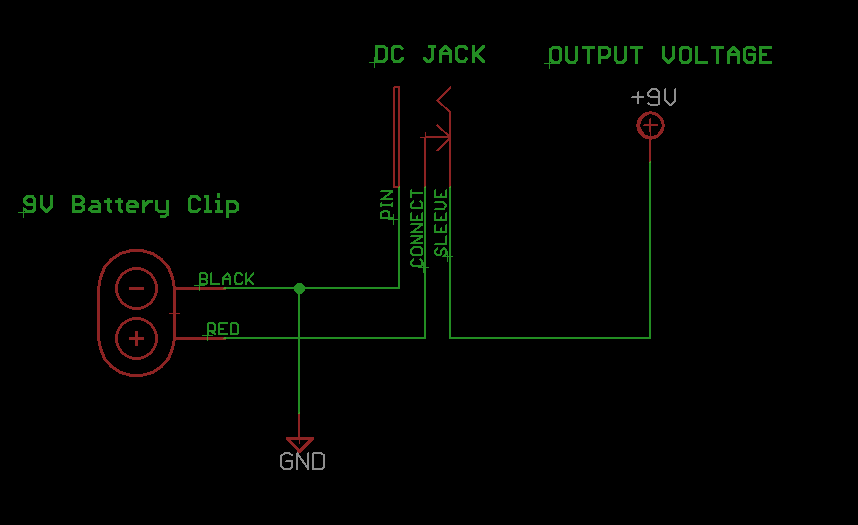
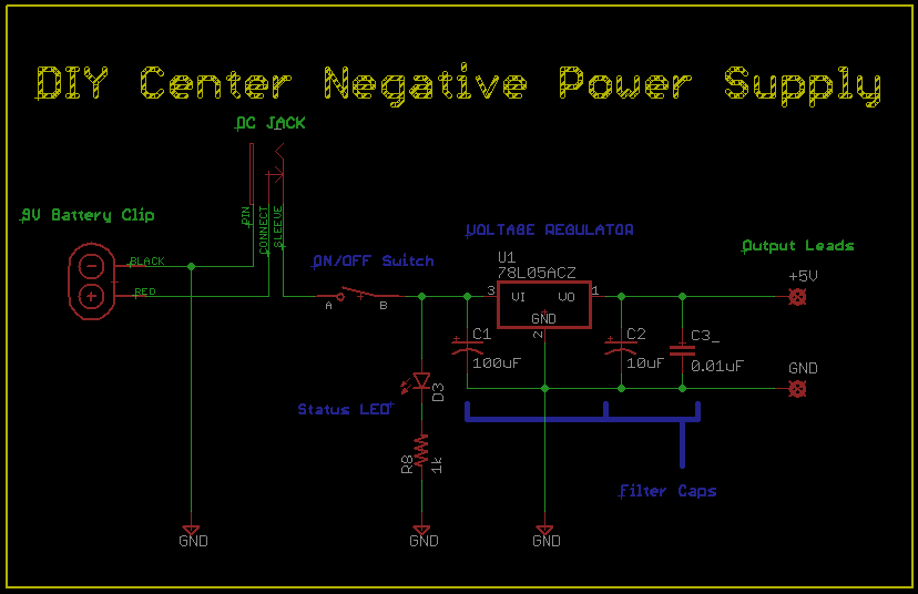
The Center Negative Power Supply is a very simple circuit. The picture above is a basic circuit snippet we can use to expand upon depending on what we are trying to accomplish.
The 9V battery’s negative terminal, the BLACK wire connects to the PIN terminal of the DC Jack, which is then a common point for GND (ground/0V). The RED wire is connected to the CONNECT terminal of the DC Jack. When no plug is present in the DC Jack, the CONNECT & SLEEVE terminals are internally connected or ‘shorted’. When an AC Adapter’s plug is inserted into the DC Jack, the CONNECT terminal is separated mechanically from the SLEEVE terminal. At this point, the battery is removed from the circuit. The fact that the BLACK wire is still connected to the circuit is not important, as that portion of the circuit is now open. You can think of the DC Jack as an event-based switch: plug in, battery off; plug out, battery on.
Simply put, using the schematic above, you either are supplying your circuit with power from the 9V Battery or the AC Adapter plugged into the jack. That +9V is only a reference point; many AC Adapters put out a higher voltage than stated on their label. What follows this circuit building block will be of much more importance than an exact voltage.
Components

These are all of the components that you will need to build a basic center negative power supply. It really does not require more than this, although there are some modifications I did just to show you some useful possibilities!
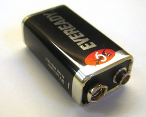
Battery
A standard 9V battery with a cool cat logo.
These can be fairly expensive, so using an AC-DC Adapter is a great way to save these batteries by using the electricity from your outlet. 9V batteries are great for backup power supplies in devices such as guitar pedals. 9V batteries also allow for portability, which is a good feature to have for some audio electronics.
9V Battery Clip
A standard 9V Battery Clip. These are readily available for purchase from Radioshack & Mouser, or they can be salvaged from toys and older electronics.
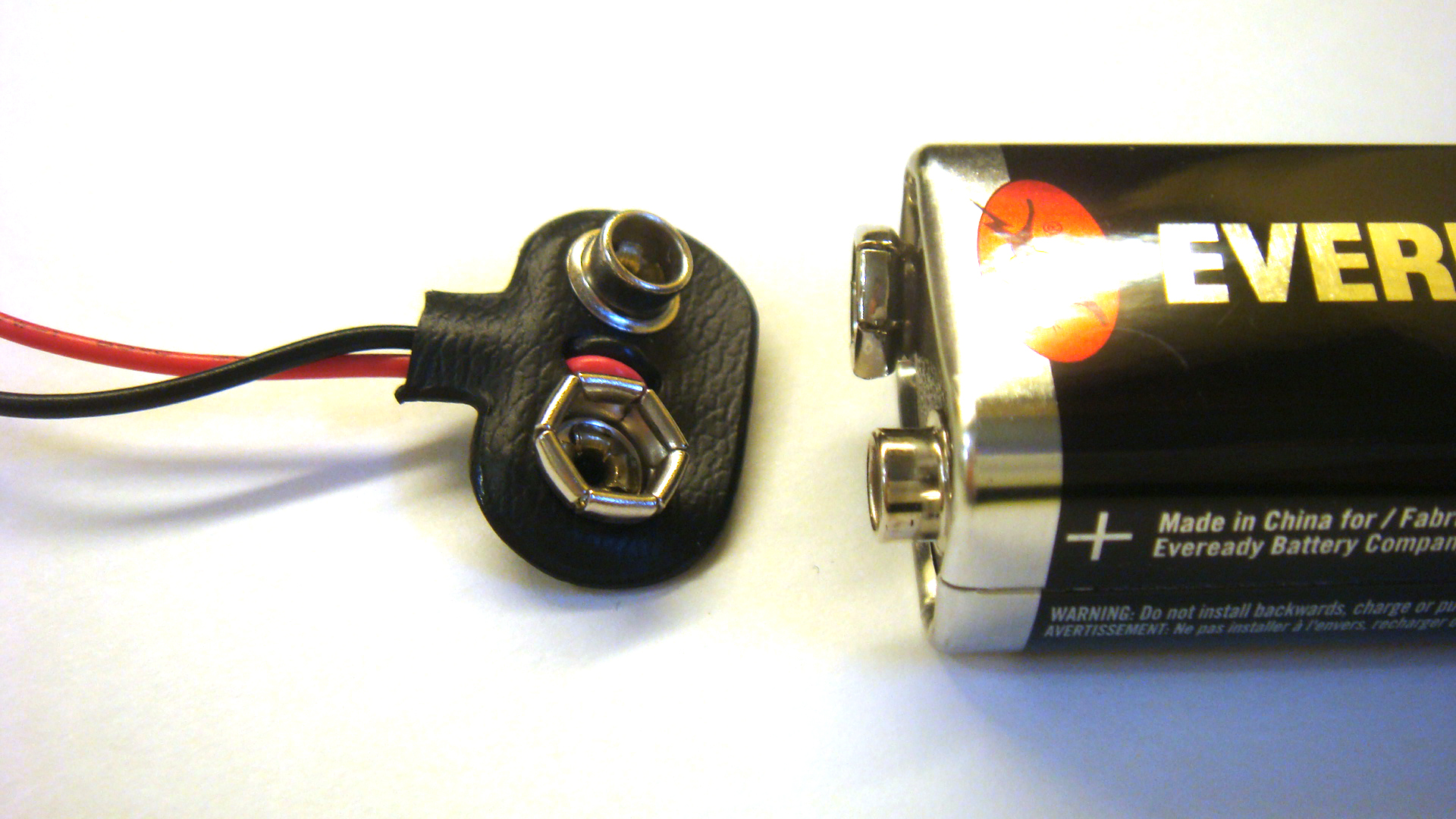
A close look at the component shows the inverse of the 9V battery’s terminals. In the picture above, you can see exactly what I mean; the positive terminal on the battery will fit snugly into the battery clip’s positive input. The red wire signifies the positive voltage connection, the black represents ground or 0V.
DC Jack
DC Jacks receive AC-DC adapter plugs (your standard wall wart) and allow for access to V+ and GND through solder terminals. With certain DC Jacks, there is a SHUNT/CONNECT terminal that gives a DIYer the option for switching between another voltage source such as a 9V Battery (that’s what we’re doing in this tutorial!).
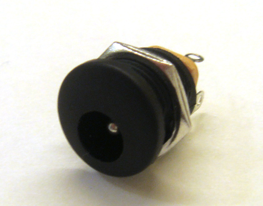
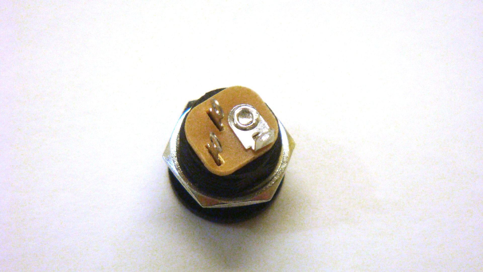

This particular DC jack that will be used in the tutorial is typically used in guitar pedal designs requiring hookup wire. The nut helps tighten it down in enclosures, which should be done last. The lip on the front of the jack requires that this part to be secured in the enclosure before wiring. Try to avoid using these types of jacks and instead save yourself some extra work by getting front-tightening DC Jacks!
Wire
I like to use color coded wire in my projects to keep track of which connection is which. It does save a lot of time! Wire can be expensive to procure the traditional way, so I suggest checking out my tutorial on tearing apart Cat 5 (Ethernet) cables to get a cheap supply of multi-colored 24AWG wire.
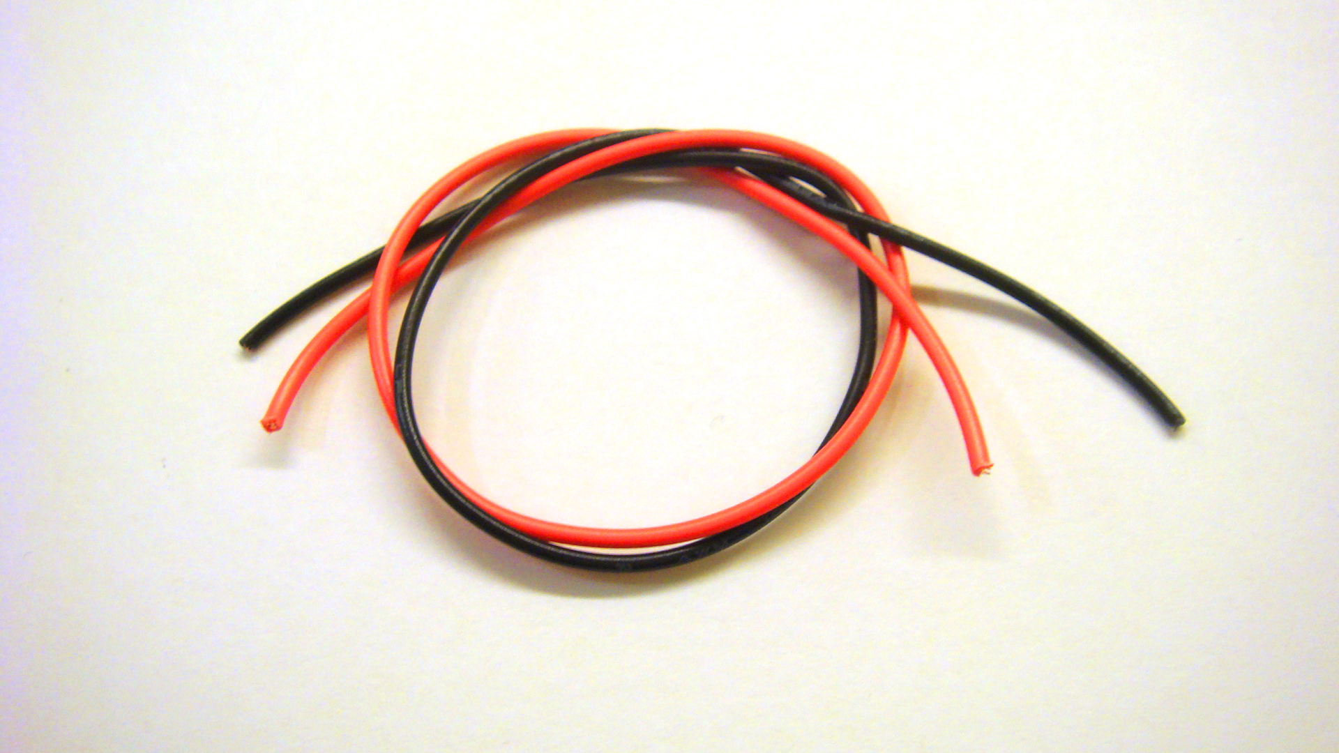
In this tutorial, I am using solid and stranded wire. I’d advise against using solid hookup wire for components that will experience a little bit of physical movement. Just use quality (not Radioshack) color-coded stranded wire and you’ll thank yourself later!

Toggle Switch (optional)
A standard purpose SPST (on/off) toggle switch.
Toggle to one side and the connections at the solder lugs are shorted, closed, “ON”. Toggle to the other and these two connections are now an open circuit, or “OFF”.
If you do not have access to a SPST switch, don’t worry; nearly all of the other types of switches (SPDT, DPDT, 3PDT) can be substituted, using only two terminals. Check out my tutorial on different types of switches here!
Tools
Multimeter
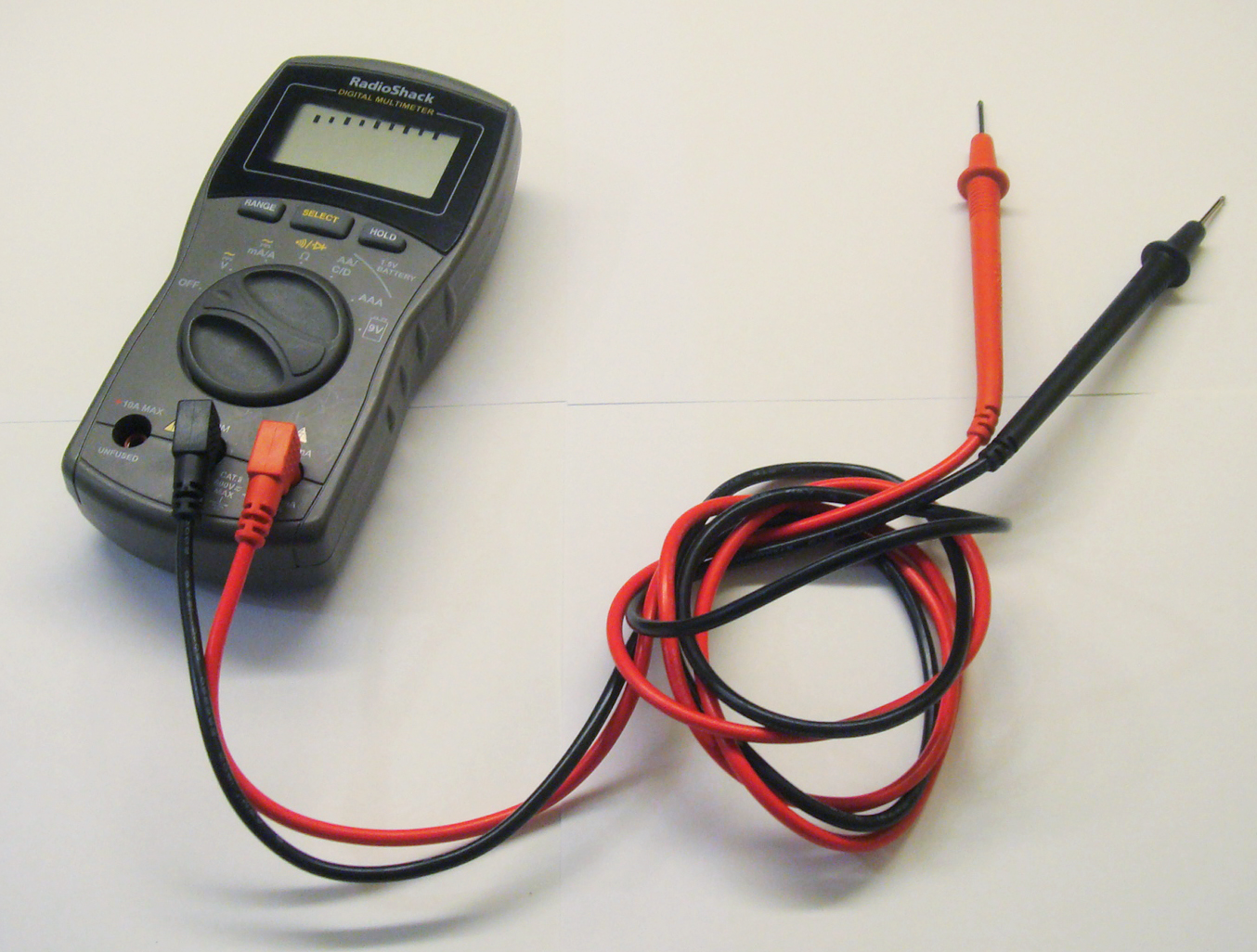
For testing voltages and connections, you will find having a multimeter around will help you immensely. In this tutorial, we will be using the Diode Test and measuring voltage.
Soldering Iron
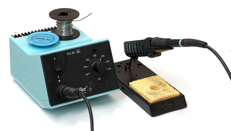
You’re going to need one of these to make your connections permanent.
Diode Test (Connectivity Test)
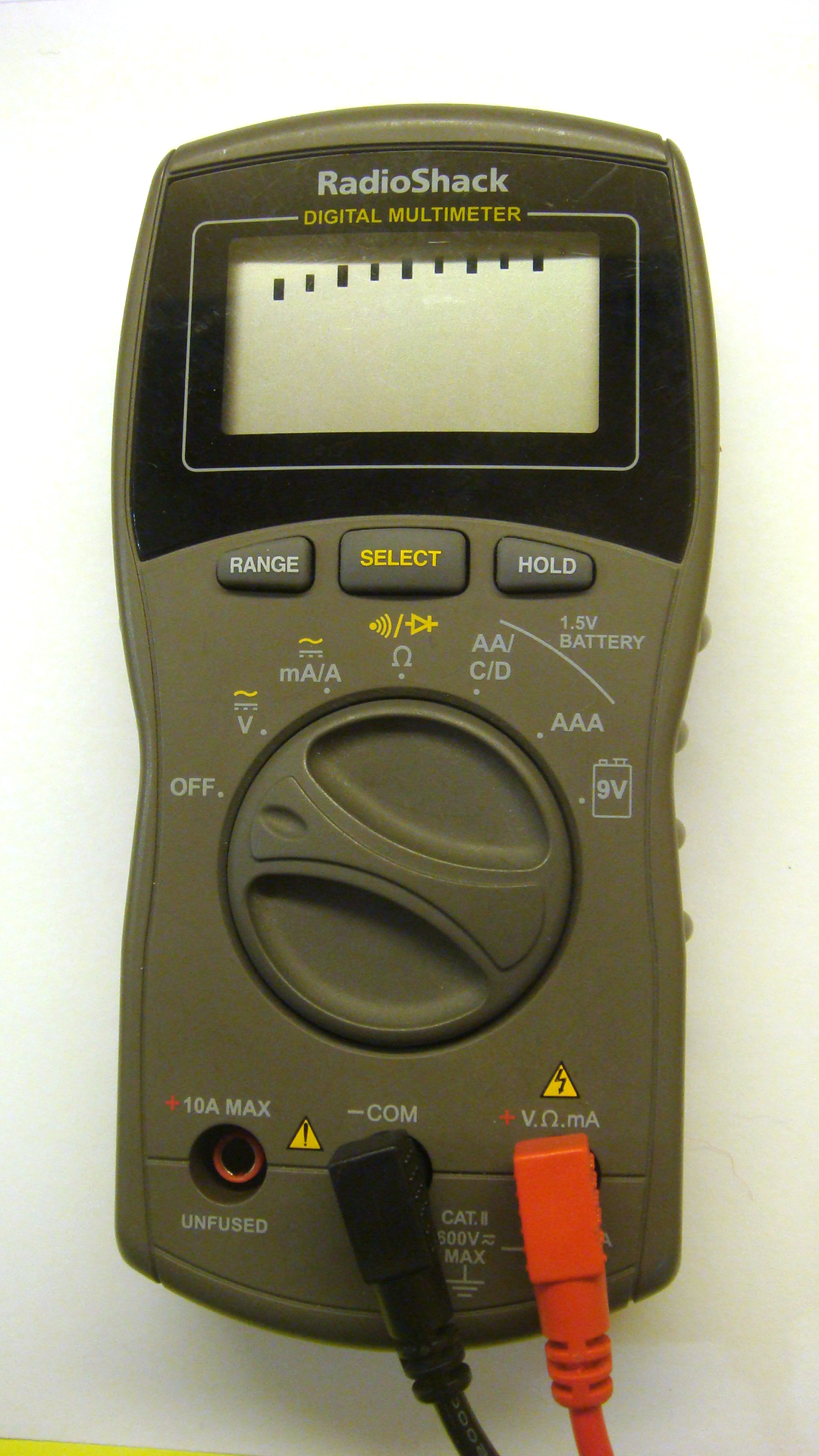
Get your multimeter out and find out how to select the Diode/Connectivity test..
On this particular multimeter, I turned the dial to the 12 o’clock position and pushed the yellow SELECT button.
Once you select the Diode/Connectivity test, tap the probes together to test that they are working.
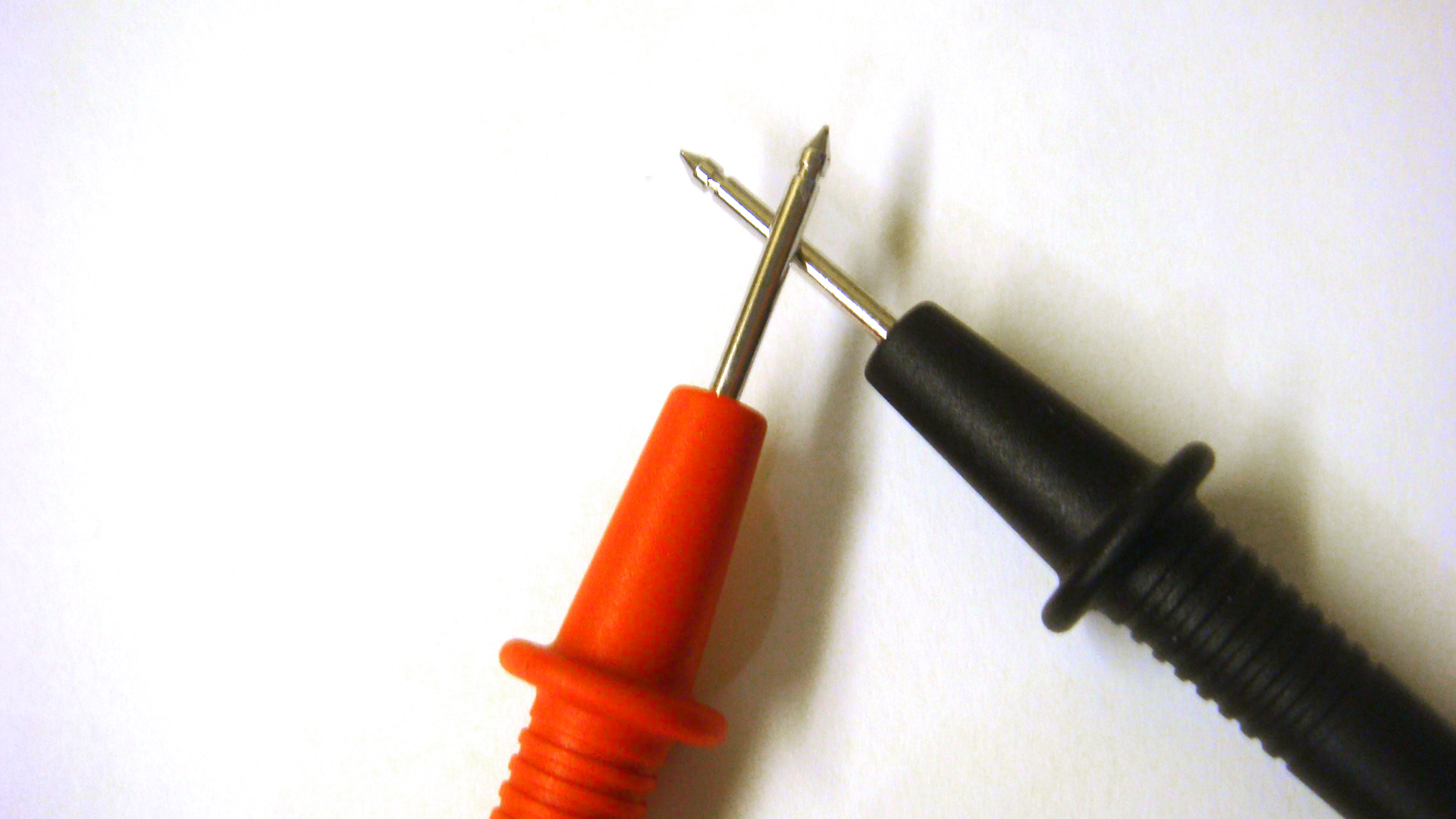
* Beep! *
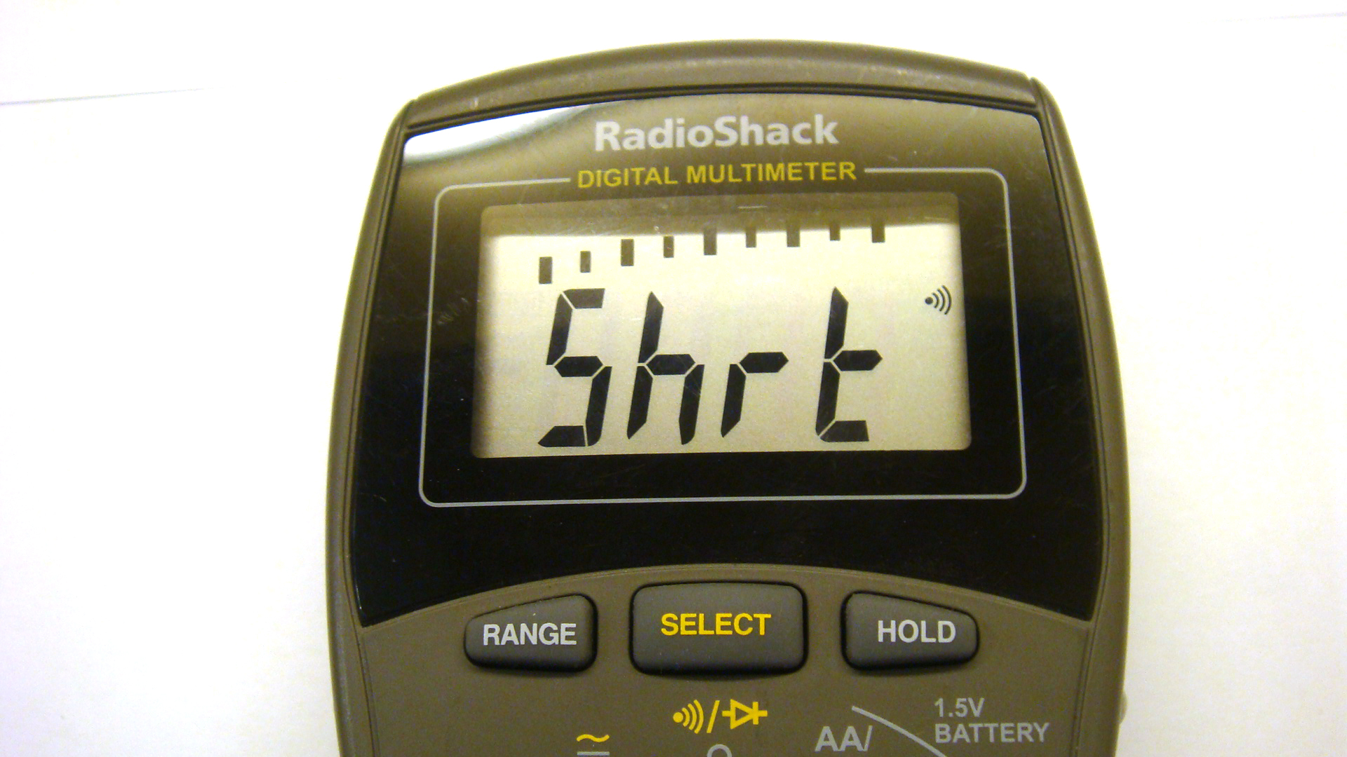
You should hear a beep or see a message that says “Short” or “Closed” or whatever it is on your multimeter.
Test the DC Jack
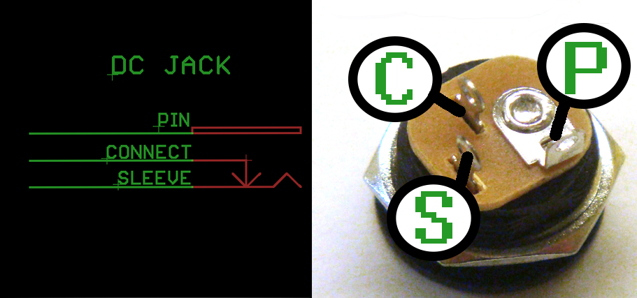
On our DC Jack, two of the solder terminals (SLEEVE and CONNECT) are connected together. Test these two terminals to confirm the internal connection.

* Beep * – they’re connected!
This is a good technique to master, especially if you are going to be salvaging parts from other electronics components or you can not find an adequate datasheet for your switch/jack/relay/other physical component.

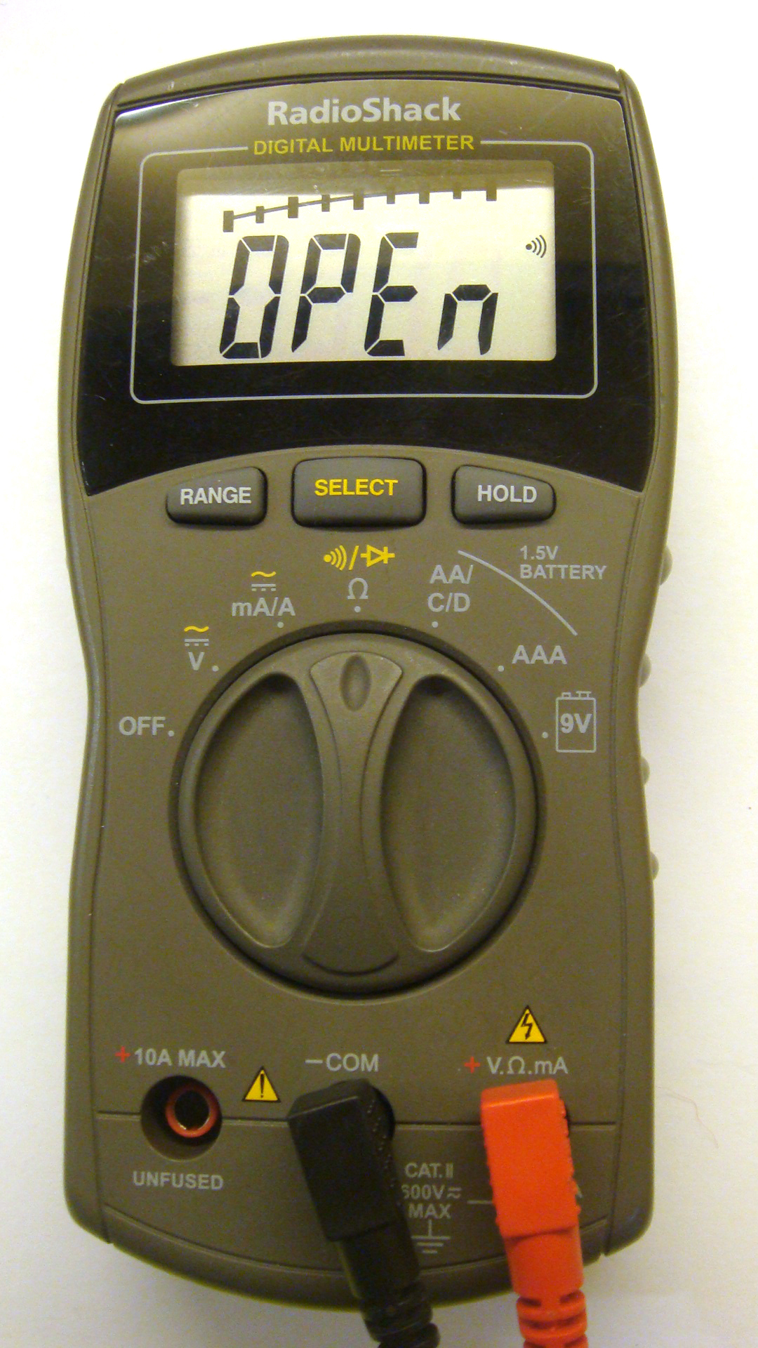
To test the DC Jack’s internal switching, I inserted a plug into the DC Jack.
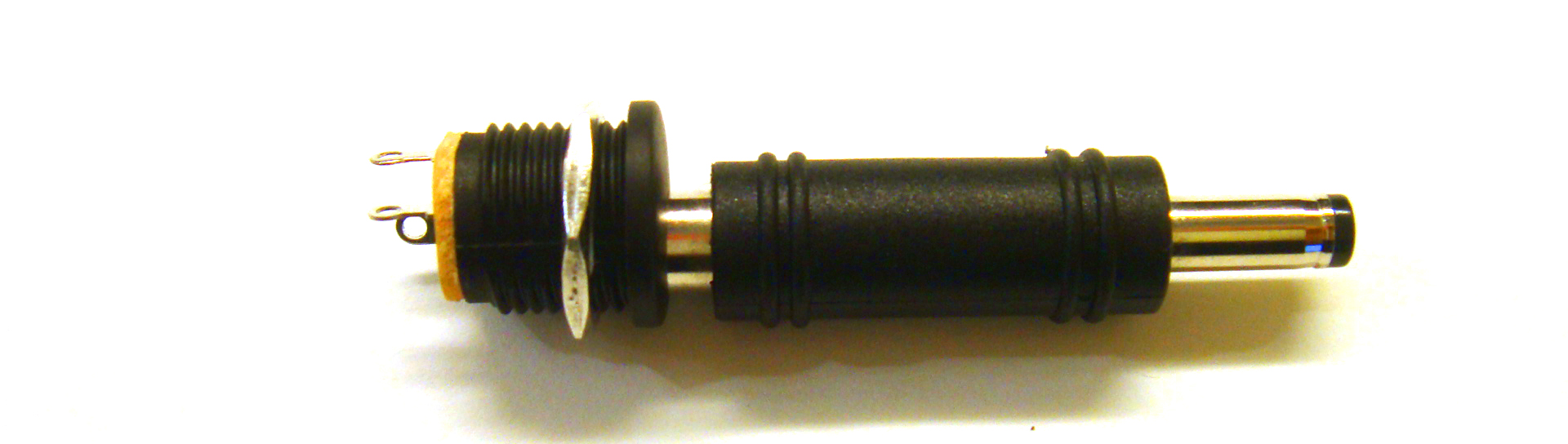

I am using a tip adapter so as to avoid using an AC Adapter.
Do not do the Diode Test with a circuit receiving power! It may break your multimeter!
Testing the previously tested solder terminals will now display this connection as “Open” or not connected.
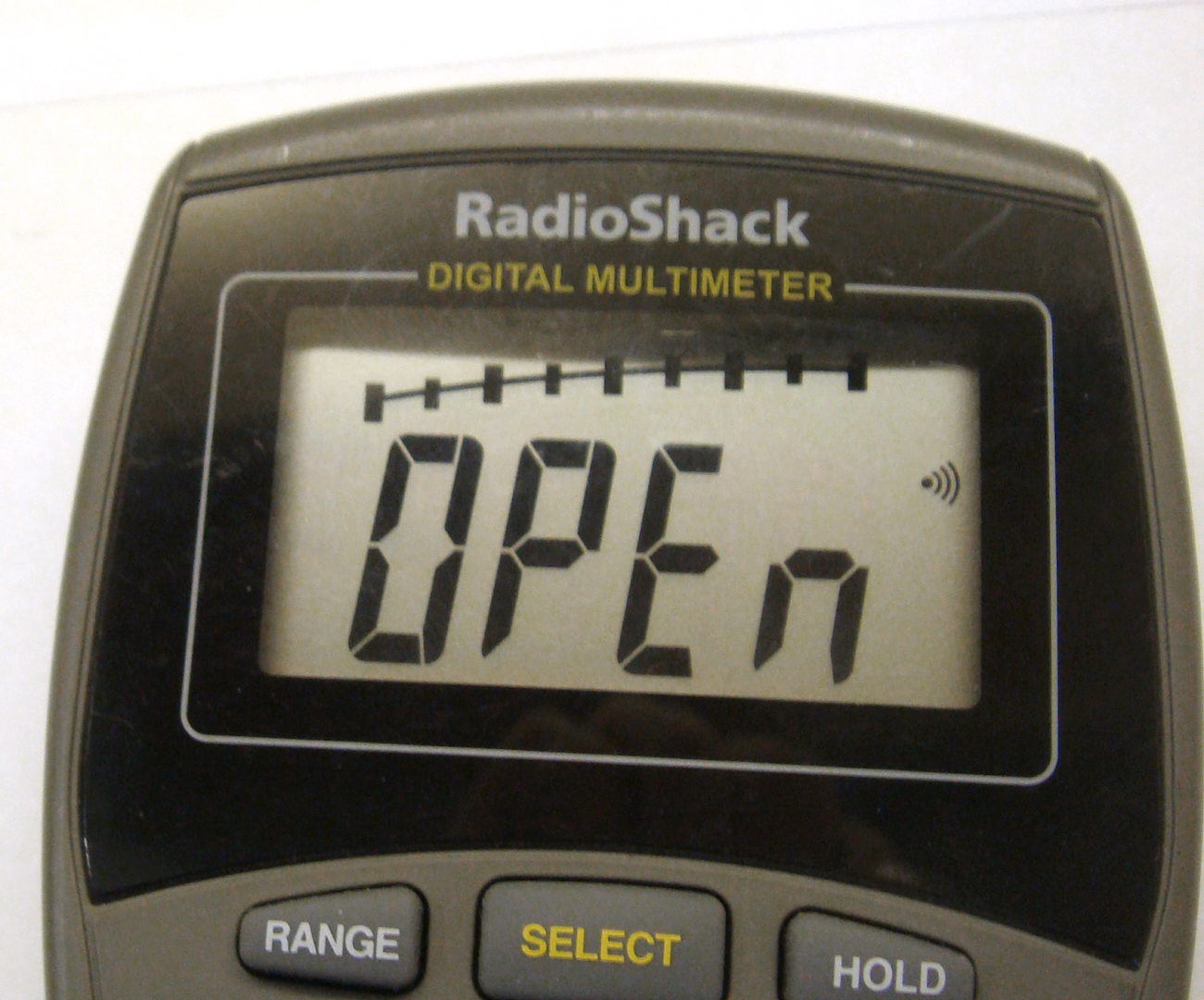
That’s exactly what we will need for our Center Negative Dual Power Supply Circuit.
If you are ever unsure about a jack’s connections, do the Diode/Connectivity test; it’ll save you some grief when you can’t figure out why your circuit isn’t getting power!
Build the Center Negative Power Supply
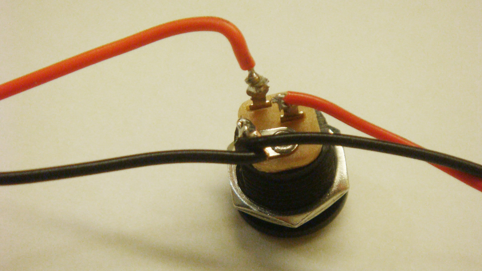
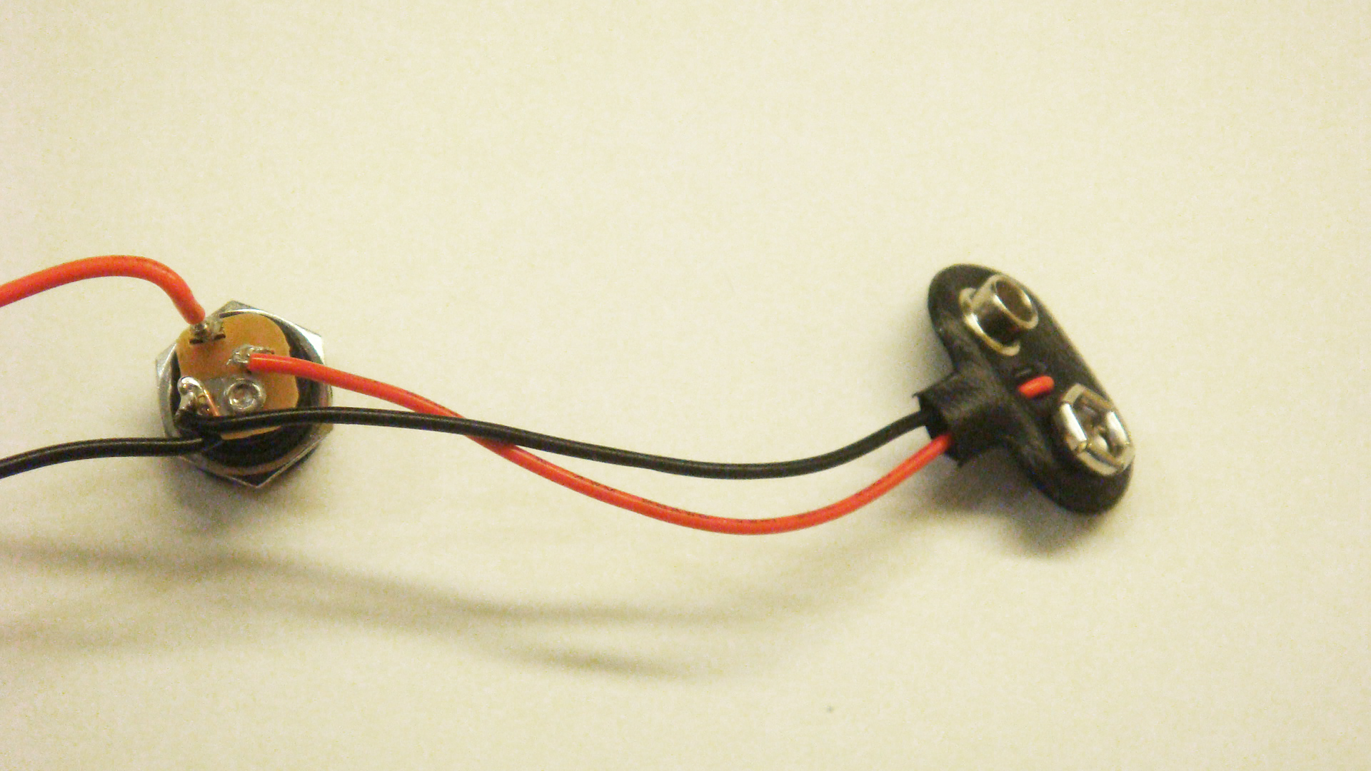
Our first task for this project is to attach the 9V Battery Clip to the DC Jack. Two leads (red and black) are also attached at this time; these will be the positive voltage and GND points we can later use to expand our circuit.

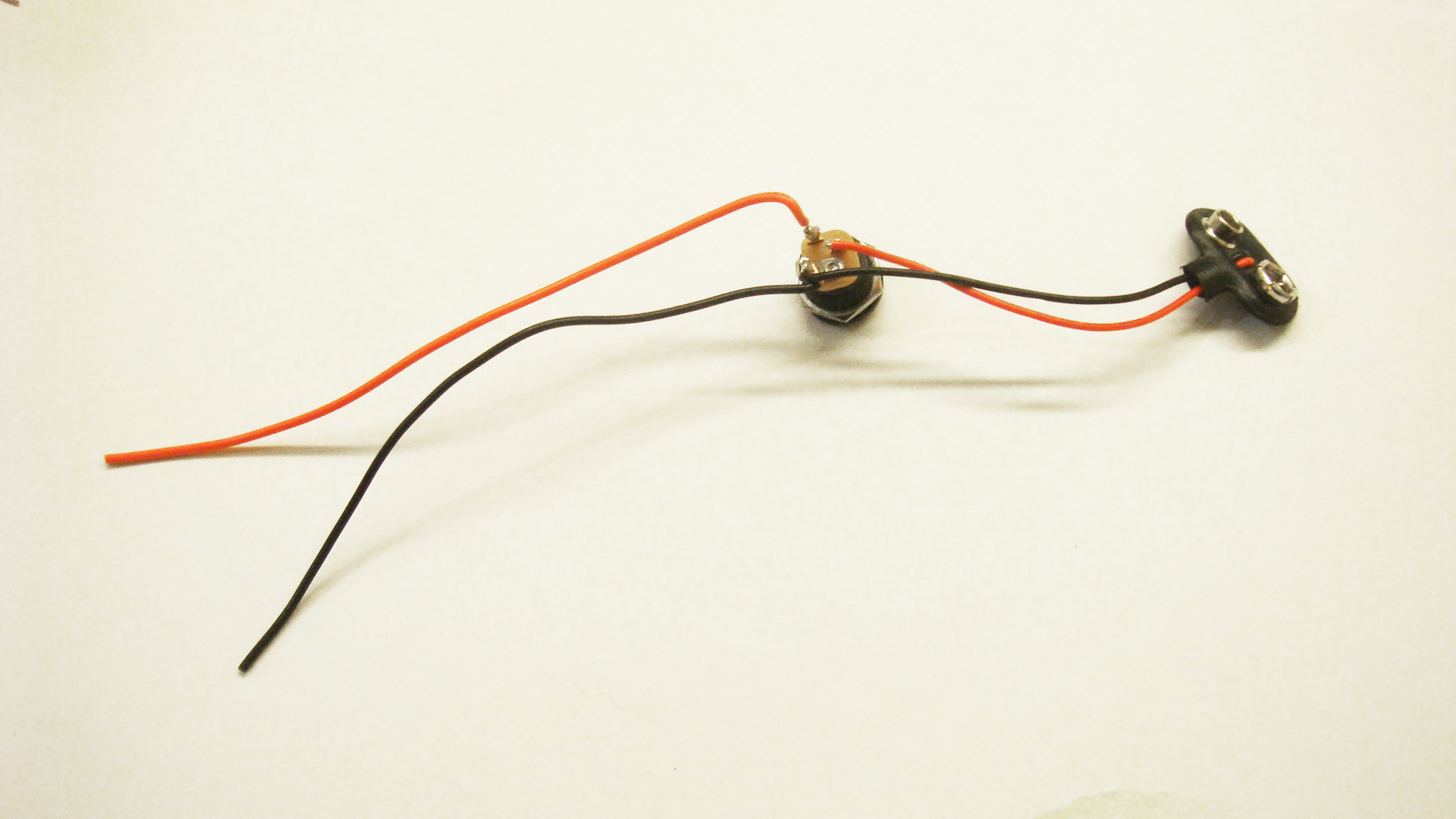
I hastily soldered up the connections as specified on the schematic. Just do a solid soldering job and you can use a glue gun or epoxy to stress-relieve the solder terminals on the DC Jack (they can be brittle).

The two black wires (BLACK from the 9V Battery Clip and a long black wire) connect to the largest solder terminal on the DC Jack, the PIN (also known as TIP) terminal. The 9V Battery Clip’s RED wire connects to CONNECT (also known as SHUNT) terminal. The remaining red wire connects to the SLEEVE terminal, the central point for where your circuit will receive power.
Add An On/Off Switch
Once you’ve got the DC Jack and 9V Battery Clip together, you’ll want to add an On/Off Switch to your Center Negative Power Supply.

Just cut the red lead wire and attach the two wires to the SPST switch’s solder terminals. It does not matter which one goes to which terminal – you can always rotate the switch to toggle in any direction you want.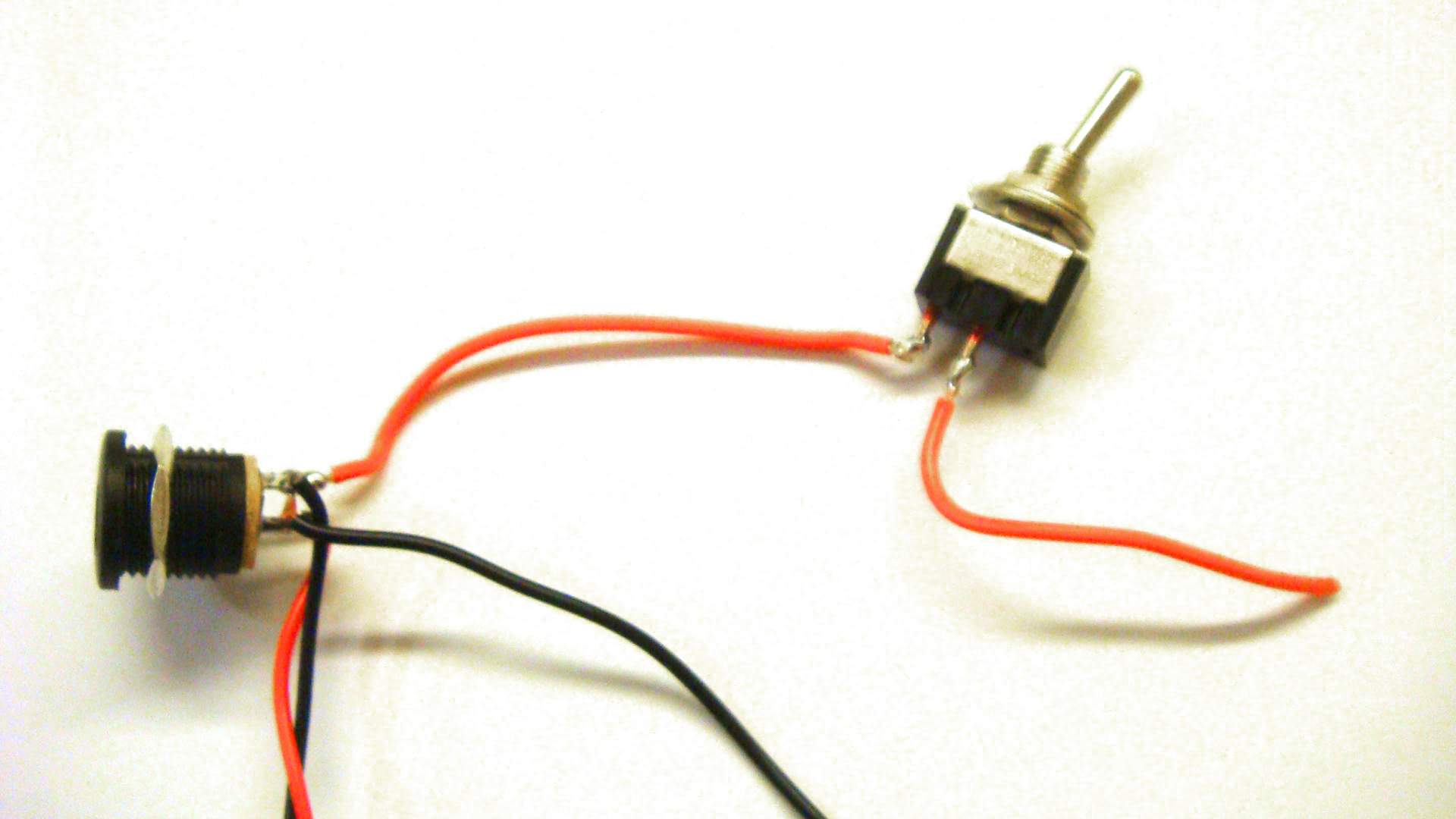
NOTE: The pictures are from a build I did in less than an hour. You may want to take some time to plan out your build’s specs before determining how much wire you will use (I used a small amount). Wire can always be cut, so go longer than you think you will need.
Test The Switch
You can test your switch with the multimeter. Simply attach both leads to the multimeter while it is set to read voltages. Plug in a battery, test, plug in a DC jack, test. You should have gotten consistent voltage readings when these power supply sources are tested independent of the circuit.
For me, I find a visual cue the best way to know if my circuit is receiving power. To expand upon the simple Center Negative Power Supply circuit, I added an LED to light up when the circuit is switched on.
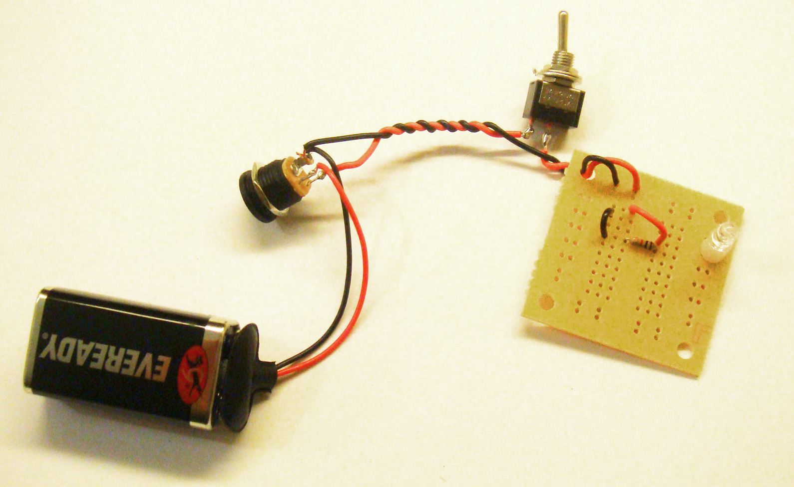

You don’t need to use a protoboard like I did; wires work great when you’re building a console-style device. I am going to add in some more functionality into my circuit with the next modification: supplying my circuit with a steady supply voltage.
Adding Voltage Regulators
AC Adapters do not always put out the voltage the manufacturer labels says. Class 2 Transformer types, the big and bulky wall warts, are often sources of noise leaking into our output signals. 9V batteries don’t always put out 9V! What’s a circuit designer to do?
Voltage regulation, that’s what you need!
Using voltage regulators, you can cut down on power supply fluctuations and instead opt for a solid output voltage. Voltage regulators require an input of about 3V above their output voltage, so a 5V regulator needs at least 8V. In the schematic below, you can see that the LM78L05ACZ is the voltage regulator surrounded by two filter capacitors. These are simple power supply reservoirs that fill in the gaps when power supply’s are shaky or a circuit demands a lot of current. An additional capacitor of about 0.01-0.1uF is often put next to the 10uF capacitor. These capacitors should be positioned in close proximity to power supply.

The final complete Center Negative Power Supply schematic is shown below. It incorporates all of the modifications discussed in the tutorial and is a great starting point for your next circuit’s power supply.

The Finished Product
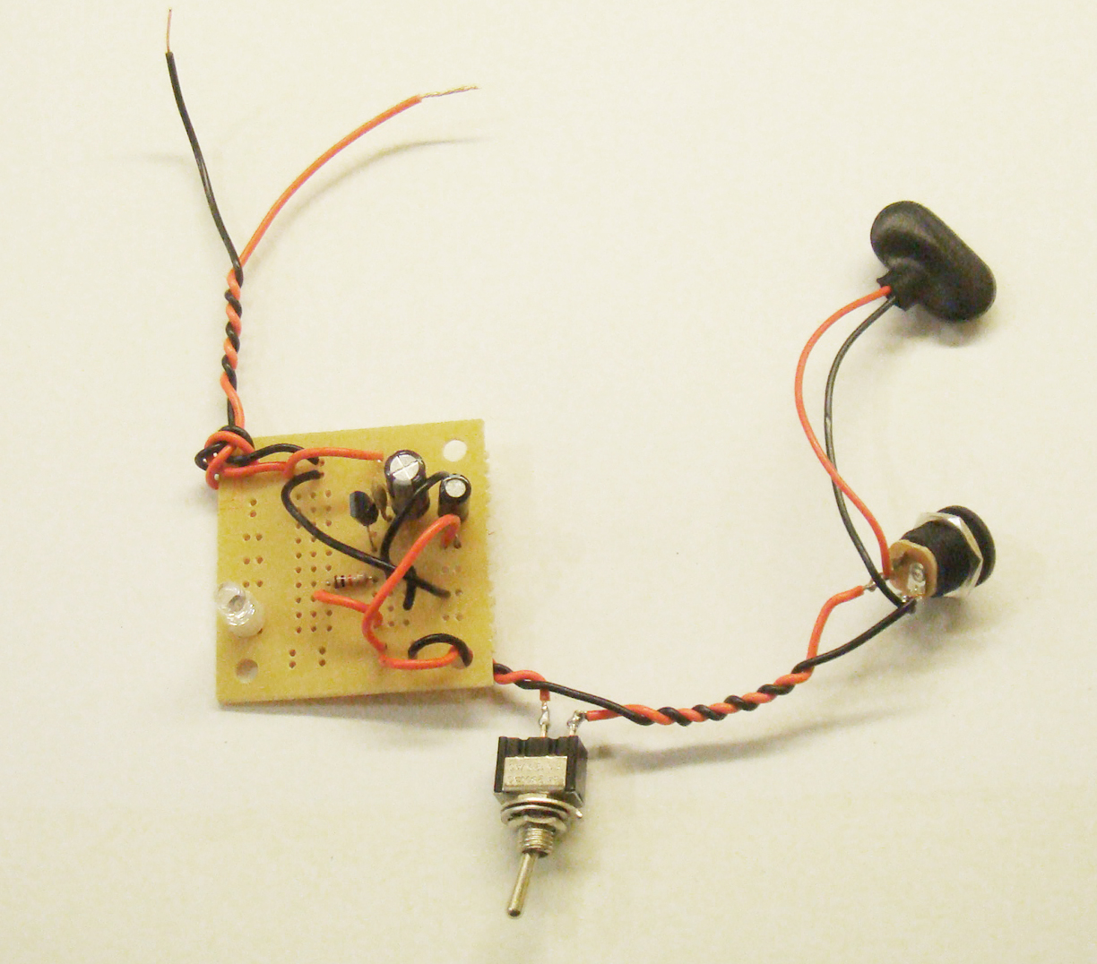
At this point, you’re done with the circuit! Case it up any way that is convenient and save a lot of time on your next electronics project with your very own center negative, regulated 5V power supply with LED indicator!


Perfect explanation!
Thanks a lot!